The attenuator on a waterjet pump intensifier pump plays a critical role in maximizing waterjet cut quality. When the intensifier shifts at the end of a stroke, the change in direction of the plunger/piston assembly causes a momentary loss of production of pressurized water. This manifests itself as a periodic drop in the cutting pressure output and often a degradation in cut surface smoothness. As water will be compressed between 11.6% and 15.0% at pressures from 60KSI to 90KSI, this extra amount of pressurized water stuffed into the attenuator volume is available during pump shift to exit the downstream port of the attenuator to supplement the outlet flow and minimize the pressure drop from the shift.
The potential downside of having an attenuator on an intensifier pump is that the pressurized water inside the attenuator contains the majority of the compressed energy downstream of the intensifier, which can be dangerous in the event of a failure of the attenuator. Properly designed attenuators will, after substantial pressure cycling, experience metal fatigue cracking which will cause a high-pressure spraying leak. While this spray can be dangerous to operators in very close proximity due to both the cutting action of the spray and the associated noise, it is generally benign if proper precautions are taken by use of personnel distancing, shielding and hearing protection. More dangerous, of course, is fast-fracture of the attenuator, which results in sudden complete release of the contained compressive energy, often accompanied by one or more pieces of ejected metal.
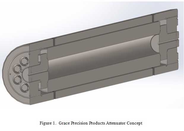
The patented (US 10,955,078) new generation GPP attenuators address these potential dangers through a combination of progressive design, state-of-the-art engineering and rigorous quality control. The basis of the design is use of a simple thick-walled cylinder acting as the main body of the vessel, surrounded by a high-strength stainless steel outer shell tube acting as both a structural frame to resist the pressure force on the end caps, as well as a shield to protect the user from the effects of a fatigue crack failure of the body. An image of the design concept is provided in Figure 1. The main closure components are retaining nuts screwed into receiving threads at the interior ends of the outer shell. The retaining nuts support the seal heads, which are axially compressed against the body ends at factory assembly through application of torque to a circular arrangement of seal energizer setscrews engaging female threads in the nut on one end.
Methods of The ASME Boiler and Pressure Vessel Code, Section VIII Division 3 have been employed throughout the design, material selection, manufacture and testing of the GPP attenuators. All attenuators are hydrostatically tested to 1.43 times the design pressure, to comply with the European Pressure Equipment Directive (PED). The compression of the heads against the body bore ends by the setscrews creates an inherently robust metal-to-metal pressure seal at both ends of the assembly. Advanced ANSYS finite element analysis (FEA) techniques have been employed to optimize the lives of the individual attenuator components, with eventual fatigue failure after a very long service period engineered to occur at the body wall as a spraying leak, with the outer shell fully containing both the spray and the noise from the leak. With its unmatched long service life and no external shielding requirement for safe operation, the GPP attenuator design is unique in the waterjet cutting equipment industry.